Why is 90 FPM Considered Standard for Cleanroom Airflow?

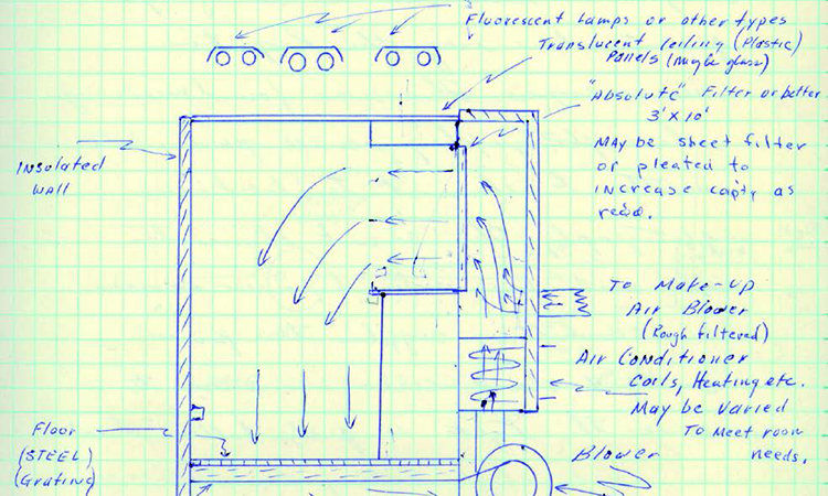
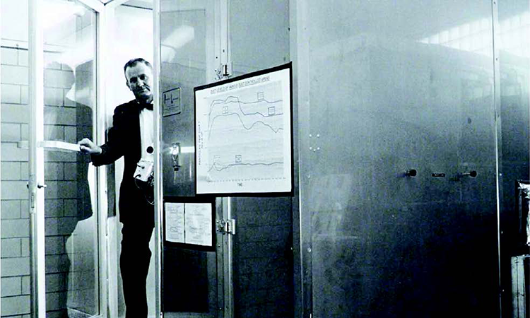
In 1961, while working at Sandia Laboratory in New Mexico, Willis Whitfield and his colleagues developed the world’s first cleanroom and clean benches. These developments were instrumental for the electronics, aerospace, and later, pharmaceutical industries, where particulate contamination had to be minimized or eliminated.
“Willis Whitfield, Claude Marsh and Gordon King discovered that the air emerging from newly developed HEPA filters did so at a uniform and predictable speed, and that the flow could carry away particles in its path,” says David Brande, lead consultant with Cleanroom Project Management, Inc. “That phenomenon became known as ‘laminar flow,’” but that term is a widely adopted misnomer.”
Rectifying that error by using the technically correct term “unidirectional” flow is important, but so is investigating how and why unidirectional airflow velocity in cleanrooms became carved in stone at 90 feet per minute (fpm).
This velocity was adequate to meet the basic criteria of controlling the particle concentration; in addition, parameters such as settling rates, personnel comfort, and noise were acceptable. If true science had been applied, however, the performance would have been tested and documented over a very wide range of velocities (25–250 fpm, for example). The approach” used in the early 1960s confirmed that 90 fpm worked, but it was never deemed optimal.
The Science
According to Claude Marsh, who worked with Whitfield, 90 fpm was established among the empirical calculations that created the first cleanrooms. “The window between 70 fpm and 100 fpm was established by the inertia of the airflow mass at 70 fpm being marginal as compared to normal personnel movements within the directional flow and the objectionable airflow at 100 fpm,” recalls Marsh. “Energy efficiency was not a consideration.”
Many suggest that the science for the 90 fpm standard may have employed Stokes’s Law and Cunningham correction factor to determine the settling rate of 5 micrometer (μm) particles in a horizontal-flow cleanroom airstream. Laboratory notes and presentations over the years suggest that with an airflow of 90 fpm, particles would remain airborne above the work surfaces farthest from the filter bank and settle less than 2 feet over a distance of 20 feet in a horizontal-flow cleanroom.
The movement of people in the cleanroom was another factor. Airflow patterns recovered quickly from the turbulence created by personnel walking at a normal rate. Also, the 90 fpm airflow velocity was not perceptible when a cleanroom worker walked toward the filter bank. Thus cleanroom personnel did not feel like they were working in a wind tunnel.

“Probably the most significant factor in Dr. Whitfield’s concept of [unidirectional] airflow was that it was a completely different idea about contamination control,” recalls Marsh. “Why try to ‘control’ contamination? Why not just eliminate it?”
According to Marsh, early attempts to measure airborne contamination in unidirectional flow rooms and cabinets yielded near-zero particle counts, even when measured biologically in petri dishes in their working environments. “Eventual improvements in particle detection and counting instrumentation continue to challenge this,” he notes.
Why try to “control” contamination? why not just eliminate it?
The Legends
Those who worked in the industry in the early 1960s have their own theories. “Gordon King told me that 90 fpm was selected as the velocity that would carry a certain size particle out of that soffit and onto the floor before it could fall onto the work surface,” says George Cadwell, retired vice president of Flanders Filters (and current consultant to the company). “Gordon couldn’t remember the size of the particle, but my good friend Vijayakumar calculated the size for me and it was somewhere upwards of 200 [μm], which makes me think that if there is any credence to Gordon’s story, the 90 fpm was designed to carry the particle out from the filter bank before it settled into the airstream.”
Cadwell also recalls that Whitfield told Bill Whyte that the reason for 90 fpm was that the fan he had made too much noise if it was run at higher volumes, but that 90 fpm was needed to wash away all the particles that were generated when several people were in the room.
Not everyone is convinced that 90 fpm is the only efficient speed for unidirectional flow. “Faster moving air is not necessarily better,” says Brande. “It may seem counterintuitive, but lowering airspeed can provide better protection for a critical area. Increasing airspeed may even be counterproductive by increasing turbulence and a reverse air flow around obstructions.”
FS 209
In December 1963, 90 fpm was codified when Sandia Laboratory produced Federal Standard 209 “Clean Room and Work Station Requirements, Controlled Environment,” which stated in a nonmandatory appendix, that clean rooms should maintain an airflow velocity of 90 fpm (within ±20 fpm).
The FS 209 committee was handpicked by Gordon King, who was in charge of unifying the different military requirements of the US Air Force, Navy, and Army to get a common specification for cleanrooms used for building warheads and guidance systems—systems with over a thousand moving parts.
According to Brande, 90 fpm became the standard for the pharmaceutical industry because the FDA used FS 209 as a reference. The 90 fpm guidance remained in force through FS 209’s many revisions (see timeline), in part because of the agency’s concern about air movement at the point of fill vs. the airflow rate measured at the filter above the aseptic operation. Questions about its universal utility were raised periodically, however.
At the Controlled Environment Testing Association’s twentieth annual meeting in 2012, for example, comments on “Response to the FDA’s Concept Paper: Sterile Drug Products Produced by Aseptic Processing” suggested that 90 fpm was “known to be a fallacy” within the cleanroom industry for over 25 years. Changing the standard, however, never seemed to get any serious industry or regulatory backing.

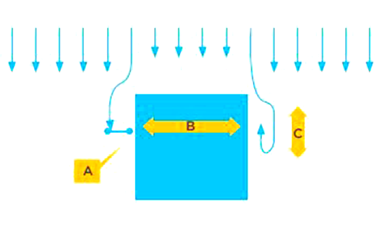
Figure: Airflow over a box diagram
The distance the airflow diverts away from the vertical side of the box can be reduced by:
- Decreasing the airflow volume/velocity directly above the box (obstruction)
- Decreasing the width of the box B
The distance of the reverse airflow C is reduced as distance A is reduced. Airflow patterns can be improved by including zones of nonuniformity, i.e., < 70 fpm

The Lums Experience
Dan Milholland of Dan Milholland and Associates recalls that the 1994 LUMS (Lilly, Upjohn, and Merck) project that investigated the use of an isolator for aseptic filling found that a unidirectional airflow at significantly less than 90 fpm was efficient in dealing with particle contamination.
The electronics industry has found that greater cleanliness can be achieved at lower air velocities due to reduced turbulence around objects in the flow path.
LUMS participants, says Milholland, built a prototype production isolator system for vial filling and did aseptic media fills in which there was no human contact with the product; glove ports enabled workers to reach into a sterile environment.
“The FDA liked the idea, it was good technology,” says Milholland. “We were working great at 40 fpm, and there was no contamination at the lower velocities in the first aseptic filling isolator.”
In the end, however, the technology was rejected by one of the participating companies because the unidirectional flow did not meet the FDA’s 90 fpm expectation. “Some in industry did not want to rock the boat,” recalls Milholland. “They wanted the first production isolators to conform to the 90 fpm guidance rather than have the unidirectional airflow move at a slower speed.” Current installations have also found improved flow with lower velocities—particularly where vertical airflow hits a filling machine top plate. Lower velocities can produce less turbulence, with a smoother transition to the flow into the air returns.
Timeline: References To 90 Fpm
- 1963: FS 209 debuted at only nine pages, which included the scope, references, definitions, and actual standard. Appendix A stated that the provisions specified were “not mandatory.” Section 40.2 set the airflow velocity preference at 90 fpm ±20 fpm.
- 1966: FS 209A retained 90 fpm in the nonmandatory appendices, but added that “individual circumstances may dictate other values.”
- 1973: FS 290B, Sec. 40.2 changed the variable unit from 20 fpm to 20% above or below 90 fpm, and stated that in “certain applications where user requirements permit, airflow velocity … may be reduced below the 90 fpm level.”
- June 1987: FDA aseptic guidelines stated that 90 fpm (±20%) was the desired velocity for aseptic operations and that “… higher velocities may be needed where operations generate high levels of particulates or where equipment configuration disrupts laminar [sic] flow.”
- October 1987: Just three months later FS 209C dropped all references to cleanroom airflow velocities.
- 2001: The last revision, FS 209 E (1992), was replaced with ISO 14644.
- 2004: A footnote in FDA’s revised Aseptic Guidelines stated “A velocity from 90 feet per minute is generally established, with a range of plus or minus 20 percent around the set point.”
Isolators Used For Semiconductors
Interestingly, “The electronics industry has found that greater cleanliness can be achieved at lower air velocities due to reduced turbulence around objects in the flow path,” explains Milholland. “The typical microelectronics room is designed to operate at 55 to 70 fpm.”
He notes that modern semiconductors are built in isolators and never exposed to air. These mini environments operate with 25% to 33% filter coverage with a filter face velocity of 65 fpm, or the equivalent of approximately 20 fpm with raised floors, rather than sidewall returns.
Semiconductor isolators operate two orders of magnitude cleaner than the FDA requirements for pharmaceutical aseptic operations. Milholland recently measured particle concentration in the duct upstream of the ULPA filters at 175 particles 0.1 μm and larger per cubic foot of air. This meets ISO Class 3 at 0.1 μm before the ULPA filters. “That’s pretty clean!” he says.


